Half Bridge: The Versatile Power Converter for High-Efficiency Applications
Introduction
In the realm of power electronics, the half bridge stands as a fundamental and versatile circuit topology that finds widespread use in various applications. Its simplicity, high efficiency, and adaptability make it an indispensable component in a diverse range of electronic systems. This article delves into the intricacies of the half bridge, exploring its principles of operation, benefits, drawbacks, and practical applications.
What is a Half Bridge?
A half bridge, also known as a push-pull converter, is a fundamental circuit configuration that consists of two power switches connected in series to a load. Each switch operates in a complementary manner, meaning that when one switch is turned on, the other is turned off.
Principles of Operation
The operation of a half bridge can be understood through the following steps:

-
Switch 1 On: When switch 1 is closed, current flows from the source voltage (Vcc) through switch 1, the inductor (L), and the load (R) to ground. During this period, switch 2 is open.
-
Switch 1 Off, Switch 2 On: In the next half-cycle, switch 1 is opened and switch 2 is closed. Now, current flows from Vcc through switch 2, the inductor, and the load to ground.
-
Freewheeling: When both switches are open, the inductor maintains the flow of current through the diode connected across the inductor. This phase is known as freewheeling.
Benefits and Why Half Bridge Matters
The half bridge offers several key benefits that contribute to its popularity in power conversion applications:
-
High Efficiency: The complementary switching action eliminates shoot-through currents, resulting in minimal power losses and high efficiency.
-
Simplicity: The circuit design is relatively straightforward, making it easy to implement and maintain.
-
Versatility: Half bridges can be used in both buck and boost converter configurations, providing a wide range of output voltage options.
-
Compact Size: The use of two switches instead of four reduces the overall size and weight of the circuit.
-
Reliability: The use of robust power switches and passive components ensures reliable operation in demanding environments.
How the Half Bridge Benefits Various Applications
The versatility of the half bridge has led to its widespread adoption in numerous applications, including:
-
DC-DC Converters: In both step-up (boost) and step-down (buck) configurations, half bridges efficiently convert DC voltages from one level to another.
-
Motor Drives: Half bridges are used to control the speed and direction of electric motors in various industrial and automotive applications.
-
Inverters: Half bridges can be used as the building blocks of voltage source inverters, which convert DC power to AC power for use in grid-connected systems.
-
Uninterruptible Power Supplies (UPS): Half bridges play a crucial role in UPS systems, providing backup power to critical loads during power outages.
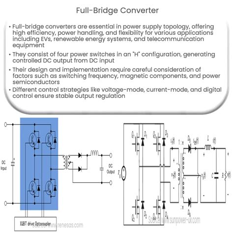
Comparison of Half Bridge and Full Bridge
While half bridges offer several advantages, they also have some limitations compared to full bridges. The following table summarizes the key differences:
| Feature |
Half Bridge |
Full Bridge |
| Number of Switches |
2 |
4 |
| Shoot-through Protection |
Required |
Built-in |
| Efficiency |
High |
Very High |
| Complexity |
Simple |
Complex |
Step-by-Step Guide to Designing a Half Bridge
To design a half bridge circuit, follow these steps:
-
Determine Power Requirements: Calculate the output power, voltage, and current requirements of the application.
-
Select Power Switches: Choose power MOSFETs or IGBTs with appropriate voltage and current ratings to handle the switching frequency and power dissipation.
-
Calculate Inductor Value: Determine the inductor value based on the switching frequency, output voltage, and ripple current requirements.
-
Select Output Capacitors: Choose output capacitors with sufficient capacitance to reduce voltage ripple and improve transient response.
-
Provide Shoot-through Protection: Use diodes or gate drivers with shoot-through protection to prevent simultaneous conduction of both switches.
-
Consider Synchronous Rectification: Employ synchronous rectification techniques to further reduce power losses and improve efficiency.
Tips and Tricks for Half Bridge Design
- Use low-resistance power switches to minimize conduction losses.
- Optimize the switching frequency to balance efficiency and component size.
- Employ soft-switching techniques to reduce switching losses.
- Minimize parasitic inductance and capacitance to improve circuit performance.
- Pay attention to thermal management to prevent overheating of power components.
Conclusion
The half bridge is an essential circuit topology in power electronics that offers a combination of simplicity, efficiency, and versatility. Its wide range of applications, from DC-DC converters to motor drives, makes it a cornerstone of modern electronic systems. By understanding the principles of operation, benefits, limitations, and design considerations of half bridges, engineers can leverage this technology to create efficient and可靠 high-power solutions.

